

Home
/
QJ57B-4A Multi-channel
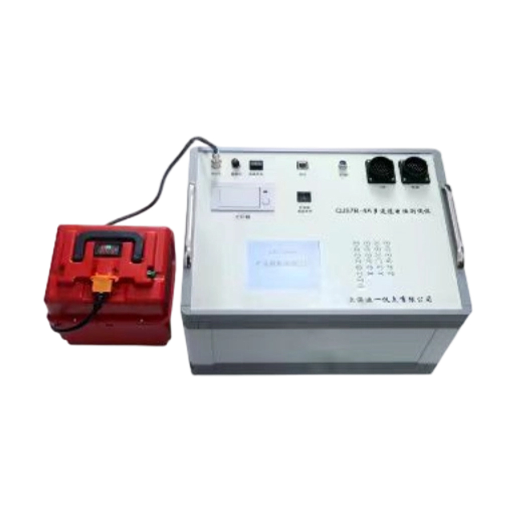
QJ57B-4A Multi-channel
1. Connect the power supply. After a 30-minute warm-up, measurements can be taken.
2. The bridge shall be operated under general favorable conditions. The surrounding air shall be free of dust and impurities that are corrosive to the product.
3. The bridge shall not be subjected to severe vibration or mechanical shock.
4. The bridge shall not be subjected to strong electromagnetic field interference.
5. Provided that the user complies with the storage, transportation, and operating instructions, the manufacturer shall be responsible for repairing the product free of charge within 12 months from the date of shipment from the factory, should the product fail to operate properly or become damaged due to poor manufacturing quality.
6. First, set the parameters on the "Parameter Settings" screen, then press the "Return" button, then go to the "Test" screen, and then press the "Test/Stop" button.
7. When submitting the instrument for calibration/verification, the standard resistor with a value of less than 10 mΩ shall be placed on the first channel for testing.
2. The bridge shall be operated under general favorable conditions. The surrounding air shall be free of dust and impurities that are corrosive to the product.
3. The bridge shall not be subjected to severe vibration or mechanical shock.
4. The bridge shall not be subjected to strong electromagnetic field interference.
5. Provided that the user complies with the storage, transportation, and operating instructions, the manufacturer shall be responsible for repairing the product free of charge within 12 months from the date of shipment from the factory, should the product fail to operate properly or become damaged due to poor manufacturing quality.
6. First, set the parameters on the "Parameter Settings" screen, then press the "Return" button, then go to the "Test" screen, and then press the "Test/Stop" button.
7. When submitting the instrument for calibration/verification, the standard resistor with a value of less than 10 mΩ shall be placed on the first channel for testing.
Quantity
-
Detail
I. Product Overview
The multi-channel monitoring system enables real-time, continuous, accurate, and multi-channel automatic measurement of monitored wire resistance values for quality control purposes. It also reserves communication interfaces for future centralized data management of multiple monitoring devices through a host computer data management system.
II. Product Function Description
a. Measuring ranges: 20 mΩ, 200 mΩ, 2 Ω, 20 Ω, 200 Ω, 2 kΩ, 20 kΩ
b. Range selection: Manual ranging and auto ranging.
c. Accuracy: ±0.05%
d. Test channels: 5 + 3 channels.
e. Length: L
f. Temperature coefficient of resistance: α20
g. Solid wire and stranded wire are selectable but mutually exclusive: if solid wire is selected, stranded wire cannot be selected, and vice versa.
h. Temperature measurement and manual temperature input are selectable but mutually exclusive: if temperature measurement is selected, manual temperature input cannot be selected, and vice versa. The temperature sensor used is PT100.
i. Equipped with a clock function.
j. Test data are automatically printed, including: Coil/Reel Number, Operator ID, Channel, Time, Temperature, Length, Rt, and R20.
k. Ethernet port: Used for communication with the host computer, transmitting: Serial Number, Time, Channel, Test Count, and Resistance Value (Rt value).
l. Power supply: DC24V
Range Test Current Resolution Measuring Range Basic Error 20mΩ 0.5A 1μΩ 0-19.999 mΩ ±(0.1%Rx+0.15%Rm) 200mΩ 0.5A 10μΩ 0-199.99mΩ ±(0.04%Rx+0.015%Rm) 2Ω 100mA 100μΩ 0-1.9999Ω ±(0.04%Rx+0.015%Rm) 20Ω 100mA 1mΩ 0-19.999mΩ ±(0.04%Rx+0.015%Rm) 200Ω 10mA 10mΩ 0-199.99Ω ±(0.04%Rx+0.015%Rm) 2KΩ 1mA 100mΩ 0-1.9999KΩ ±(0.04%Rx+0.015%Rm) 20KΩ 100μA 1Ω 0-19.999KΩ ±(0.04%Rx+0.015%Rm) -
Customer ReviewsNo comments